| [zurück] | Spectra Physics Argon Ionen Laser |
[vor] |
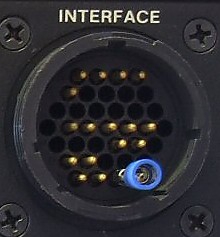
Der Interface Stecker.
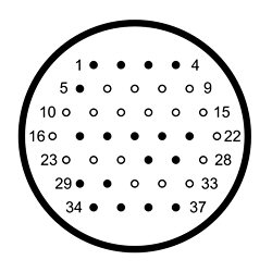
Die Belegung des Steckers habe ich von Samīs Laser FAQ übernommen.
| Pin | Beschreibung |
| 1 | Reference Return |
| 2 | Reference Input 0-3 V |
| 3 | Reference 3 V Supply Sensitivity is approximately 5 mW/V in Power Mode or 5 A/V in Current Mode. Use 100 ohm pot or external source. For pot, pin 1 is CCW end. |
| 4 | Cable shield/System Ground |
| 5 | Modulation Input, 0 to 10 V |
| 6 - 16 | Not used |
| 17 | Common Current Monitor+ |
| 18 | Common Current Monitor- Scale is 0.1 V/A between pins 17 and 18 which is across 0.1 ohm resistor in series with plasma tube. These pins cannot be grounded or measured with respect to ground because they are referenced to the AC line. Use the buffered signals, below. |
| 19 | +15 VDC |
| 20 | -15 VDC |
| 21 | +/-15 V (Return) Regulated voltages for user use, 100 mA max, only used when system is configured as an earlier model 261B-03. |
| 22 - 25 | Not used |
| 26 | Current Monitor+ |
| 27 | Current Monitor- 0.1 A/V from low impedance floating buffer, may be connected to voltmeter (differential) of 1K ohm or higher input impedance. To keep noise pickup low, do not ground either pin. |
| 28 | Not used |
| 29 | Power Monitor+ |
| 30 | Power Monitor+ 0.2 V/mW from low impedance floating buffer, may be connected to voltmeter (differential) of 1K ohm or higher input impedance. To keep noise pickup low, do not ground either pin. |
| 31 - 33 | Not used |
| 34 | Standby (Source) |
| 35 | Standby (Return) - Reference for pin 34 Switch to select Standby or Run. Shorted for Standby, open for Run. To configure as earlier model 261B-03: O V for Standby, +24 V for Run. |
| 36 | Interlock (Source) |
| 37 | Interlock (Return) - Reference for pin 36 Switch to turn laser on and off. Open for laser Off, shorted for laser On. |
Der Stecker zum Laserkopf.
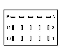
Die Belegung des Steckers habe ich von Samīs Laser FAQ übernommen.
| Pin | Beschreibung |
| 1, 2 | Cathode/Filament 1 |
| 3 | Safety/Earth Ground |
| 4, 5 | Cathode/Filament 2 |
| 6 | One side of Fan |
| 7 | Other side of Fan/one side of Thermal Interlock |
| 8 | Anode |
| 9 | Other side of Thermal Interlock |
| 10 | Anode |
| 11 | One side of Model Sense Resistor in head (not on all units) |
| 12 | Other side of Model Sense Resistor in head (not on all units) |
| 13 | Photosensor and feedback shield |
| 14 | Photosensor Collector |
| 15 | Photosensor Emitter |
| [zurück] | [Inhaltsverzeichnis] | [vor] |